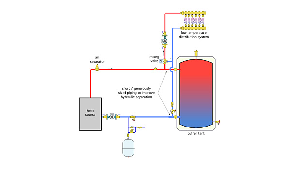
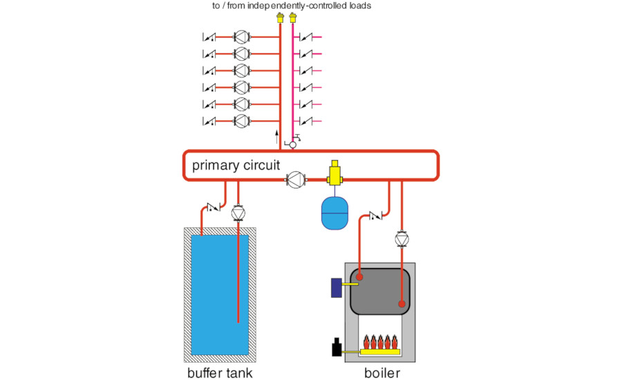
Schematic Chilled Water Buffer Tank Piping Diagram

Heatspring Magazine 2 Pipe Versus 4 Pipe Buffer Tank Configurations

Impovements To Ergomax Buffer Tanks
Alternate Methods To Pipe A Buffer Tank 2014 10 22 Plumbing And Mechanical
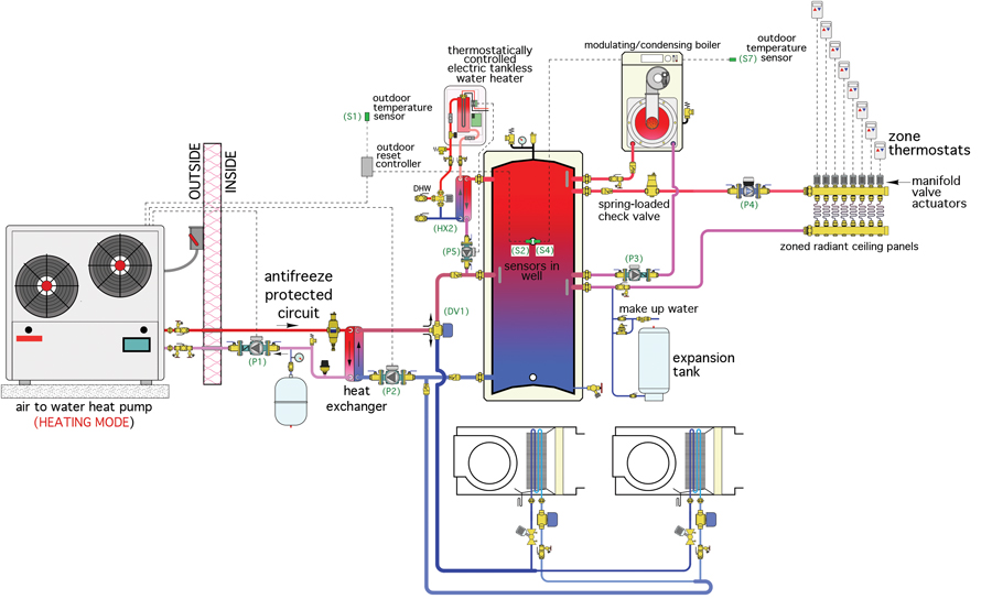
Heat Pump Plus Hpac Magazine
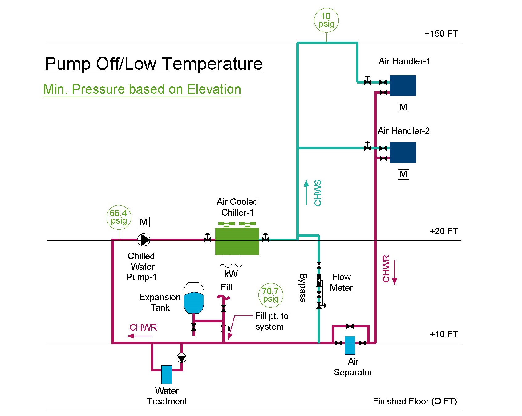
Expansion Tank Design Guide How To Size And Select An Expansion Tank For A Chilled Water System

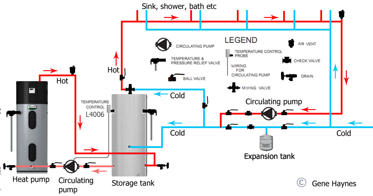
Hot Water Storage Tank Piping Diagram Water Storage Tanks Reverse Osmosis Water Water Tank
Po box 55 cheswick pa 15024 phone 724 274 5430 fax 724 274 5448.
Schematic chilled water buffer tank piping diagram.

Ecopower Principles

Spec Check Issue 1 Buffer Tanks Masterflow Solutions

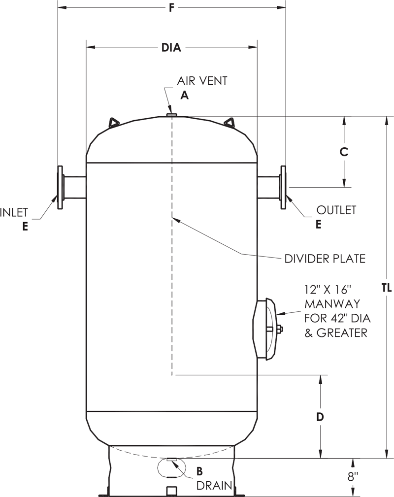
Wheeler Tank Manufacturing Inc
Asme Storage Tanks Elbi Of America Houston Tx

Buffer Tanks For Cold And Hot Water Systems Wessels Company

Water Storage Tank Piping Diagram For Hot Water Storage Tank

Different Ways To Pipe A Thermal Storage Tank 2016 03 22 Pm Engineer

Residential Plumbing Diagrams Hot Water Circulation Residential Plumbing Hot Water Plumbing
How To Install Two Water Heaters

Chilled Water System Basics Hvac Commercial Cooling

Design Selection Cooling Towers Closed Circuit Cooling Towers Evaporative Condensers Aircoil Evaporators Ice Thermal Storage Systems Baltimore Aircoil Company

Electric Boiler For Forced Hot Water Heat System Google Search Water Heater Tankless Water Heater Water Heating Systems
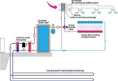
Water To Water Heat Pumps

Everything You Wanted To Know About Glycol

The Finer Points Of Applying A 2 Pipe Buffer Tank 2017 04 28 Plumbing And Mechanical
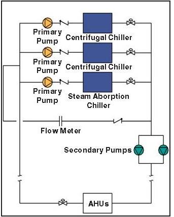
Making Them Work Primary Secondary Chilled Water Systems
Https Www Engproguides Com Ruleofthumbcalculator Pdf

Piping Diagram Tankless Water Heater Trusted Wiring Diagram U2022 Rh Soulmatestyle Co Water Heater Storage Tank With Pipin Storage Tank Water Heater Gas Supply
Https Encrypted Tbn0 Gstatic Com Images Q Tbn 3aand9gcs0ctrnc Dn Uynfl0svicrqgtse27jhzqn3d1byy3emf8ohyma Usqp Cau

Open Vented Hot Water Cylinders

It S Less Complicated Than It Looks This Schematic Drawing Is Probably The Most Efficient W Hydronic Heating Systems Radiant Floor Heating Solar Water Heating

Steam Schematic Sign Google Search Electrical Wiring Diagram Steam Boiler Electrical Wiring

Air Source Heat Pump And Solar Water Heating Combined Heat Pump Hydronic Heating Systems Hydronic Heating
The Do S Don Ts Of Hydronic System Design 2000 05 03 Pm Engineer
Source : pinterest.com
